Simple 10M Magnetic Loop Antenna by Ron Brillinger VE7RFB
Now that cycle 25 is on the upswing we can look forward to increasing amateur radio activity on 10 meters, and once again contacts with stations in far away places, even if we are limited in transmitter power output, or are unable to erect a full size and perhaps highly visible outdoor antenna. The challenge is really that of reception of the signals from those far away places rather than getting a transmitted signal to that DX station. Given that few of us can erect multi element yagi antennas, (or any other highly visible antenna for that matter), the magnetic loop antenna appears to be a prime candidate for an acceptable solution to the problem of participating in amateur radio activity, while living in a less than ideal location. This is particularly true if the design and construction of the loop antenna is optimized for one particular band like 10 meters for example.

I live in an apartment building, and as such I must contend with high levels of QRN from neighbouring fluorescent lamps, TV sets, mix-masters, computers, (and the list goes on). The Magnetic loop antenna could give you a real advantage for reception in such an environment, and at the higher frequencies, like 10 meters, the transmit efficiency of a small loop can be almost up to par with a full size dipole. Something approaching 90% (-0.5 dB below 100%).

My latest small transmitting loop antenna project is simple because it is designed for one band. It is inexpensive to build, and actually out performs the multi band ATU loop you can see in the background of the above photograph.
What do you need to build it ? Well the essential ingredient is a ten foot length of 1/2” copper tubing. It is actually 5/8” O.D. and is relatively easy to form into a loop of about 31” in diameter. I used an electrical conduit type “C” access fitting to bring together the copper loop, gamma matching network and SO239 for a 52 ohm RG8 coax connection to my radio. This fixture, can be supplied made of either cast aluminum or PVC. It will need some holes drilled to accommodate other bits and pieces, and perhaps a bit of filing to ease the copper tubing through the assembly; but more about that later.

You will notice that the ends of the copper tubing overlap by about 22” at the top of the loop. They overlap but don’t touch because they are held apart at a constant distance by 3 clips. I used plastic “chair ganging” clips. They snap on to the copper tubing and hold firmly but still allow adjusting the overlap by push and pull for tuning. And yes you are right, what we have constructed is a variable capacitor of about 20pf at the top PIX 3 “high voltage” end of the loop. The clear plastic end caps you see on the copper pipe were found on the SO239 fittings I purchase for my loop projects. They fit the tubing perfectly and help to rain proof the assembly.
The bottom of the loop, (the high current point), passes through the conduit fixture and it is there that we connect the coax from my transceiver with the “gamma” matching section that feeds the loop. You can see this completed assembly in the following photograph.

And below is a drawing showing the location of holes to be drilled in a type C conduit fitting to accommodate the SO239 and feed-through connector to the “gamma” match. If you are going oto mount this fixture to a tripod or something similar you should install the mounting nutoand bolt at the bottom before passing the copper tubing through.


When assembled you will probably want to weather proof the copper tubing entry points, as I did, with silicon seal.
Now lets have a look at the matching network.

I chose a 13” length of copper “pipe hanging” strap to form the gamma matching section. A two inch brass bolt temporarily placed through various holes in the copper stripping and contacting the loop’s surface allowed me to locate the best match. Finally I fastened this bolt to the copper strap with a brass nut, and soldered the bottom end to the copper loop antenna. This took a fair amount of heat, and my 350 watt soldering gun was just up to the task.

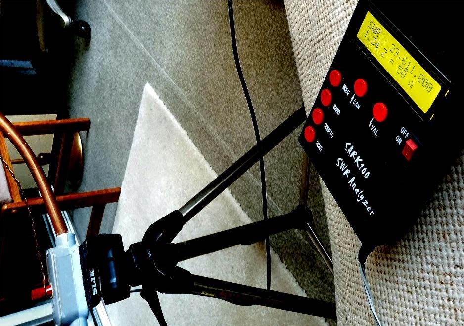
The result I obtained on my antenna analyzer at this point are shown below. At 28,280 kHz the measured SWR was 1.2:1 The antenna does have a high Quality (Q) factor and that contributes to its efficiency; but still, it does exhibit a reasonable bandwidth. Something approaching 250 kHz. You can push or pull the overlapping sections of tubing to get the centre frequency you desire for operation in the 10 meter band.
And yes, the magnetic loop antenna does exhibit a measurable advantage when employed in a location exhibiting considerable QRN.
The observed difference between this antenna and thers antennas is a 1 to 2dB decrease in noise sensitivity. But as they say in the advertisements, your results may vary.

Over all, this seemed to be a good point to pause my project. VE7RFB Ron


