Congratulations
Congratulations to the 18 new Amateur Radio operators who passed their exam tonight.

Congratulations to the 18 new Amateur Radio operators who passed their exam tonight.
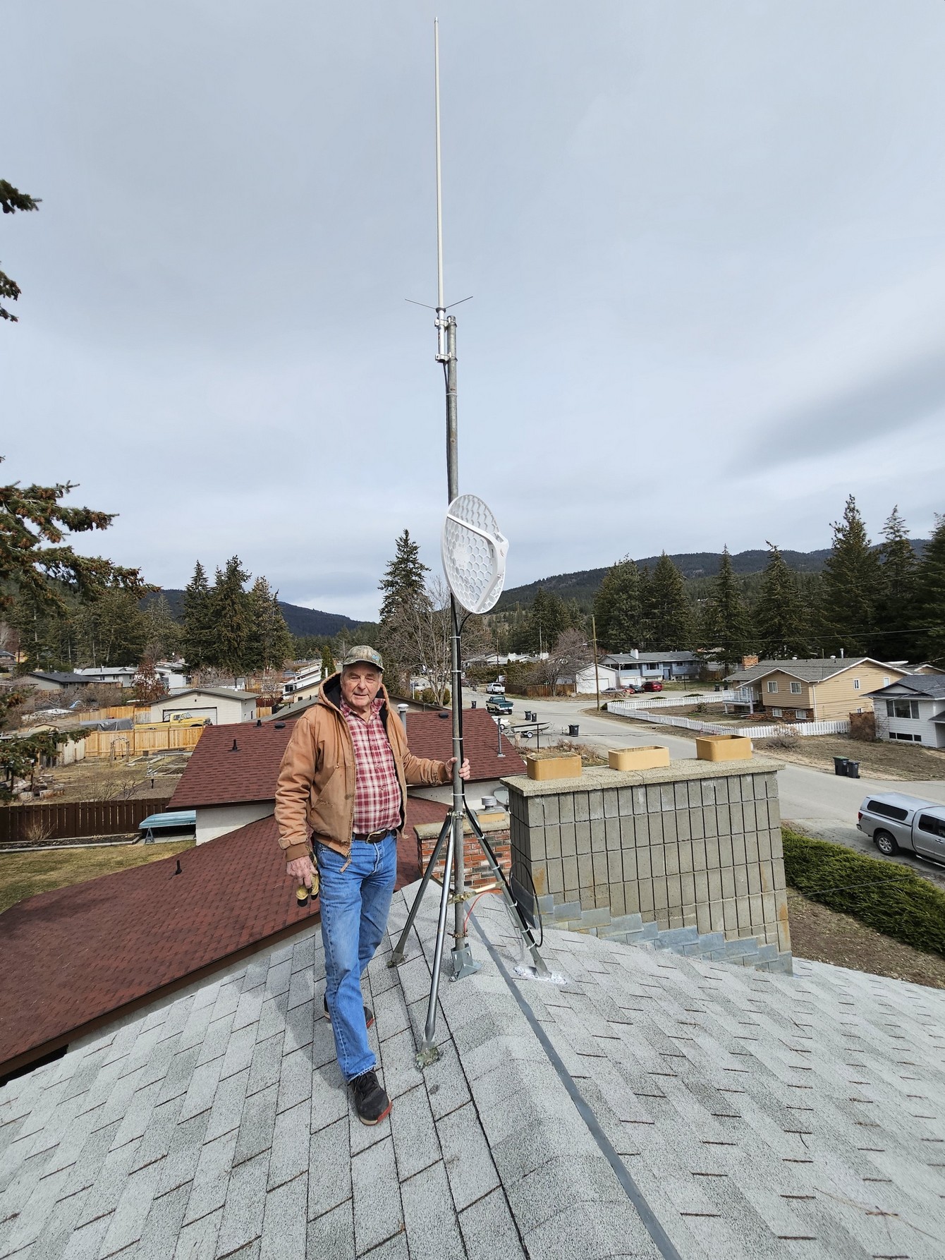
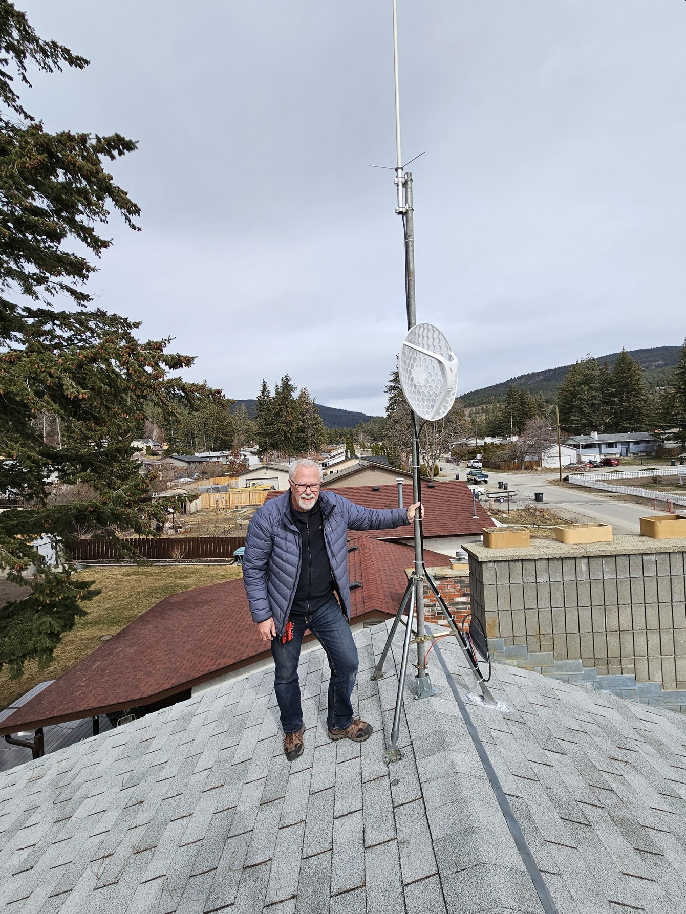
Greg VE7CD had a work party at his place, moving an antenna and mounting a hamwan dish.
Many thanks to Doug VE7VZ, Bob VA7RGM, Merlyn VE7MZP, Dave VA7MD, and John VE7JXC
The SMALL LOOP ANTENNA chronicles VE7RFB 2023-02-18
Before moving to Kelowna, (about 25 years ago) I retired to a small farm in Ontario and raised “antennas“. Mostly large antennas. I even had a big 20 meter Rhombic.
Upon moving to Kelowna, I was introduced to that marvellous concept known as the HOA and all its by-laws regarding antennas.
Thus began the quest for a small antenna that no one would complain about; but at the same time, a small antenna that actually worked.
Gradually this mythical antenna emerged as “loop antenna”, and as a bonus it turned out that it could have a noticeable advantage in the reduction of local QRN.
Pix1
The first trial:
The aluminum eaves-trough of my initial home in Kelowna became a relatively large, horizontal, loop. Each section was electrically bonded together with self tapping screws to reduce resistance at the joints.
It turned out that the resultant loop was self resonant near middle of the 160 meter band, but I used a tuner to resonate that loop to the 40 meter band.
And it did provide excellent coverage for a digital BBS link to the West Coast from Kelowna.
Pix 2
A similar concept but smaller, is shown above. It too is “loop shaped” (but technically, not really a “loop” as it is open at one end). (It is more like a “bent” end fed antenna).
The aluminum clad siding on our winter home behaved sort of like a back plane and increased the over all efficiency notably – probably by reducing ground loss.
This aluminum sheeting actually appeared to work as a reflector, (at least on 20 meters) to aim signals at South America.
Connected to the MFJ auto tuner, that you can see in picture 2, it produced a relatively low SWR on 40 – 15 meters.
Pix3

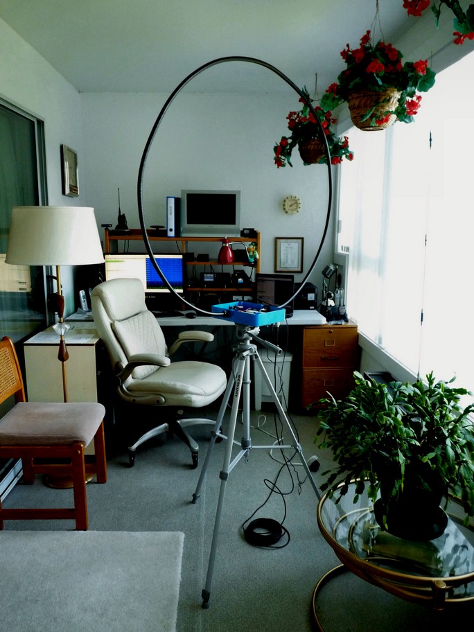
Eventually in Kelowna, Margaret and I, moved into a condominium apartment. Now we had the additional problem of electrical noise from nearby appliances, and a challenging array of electrical noise sources located just outside.
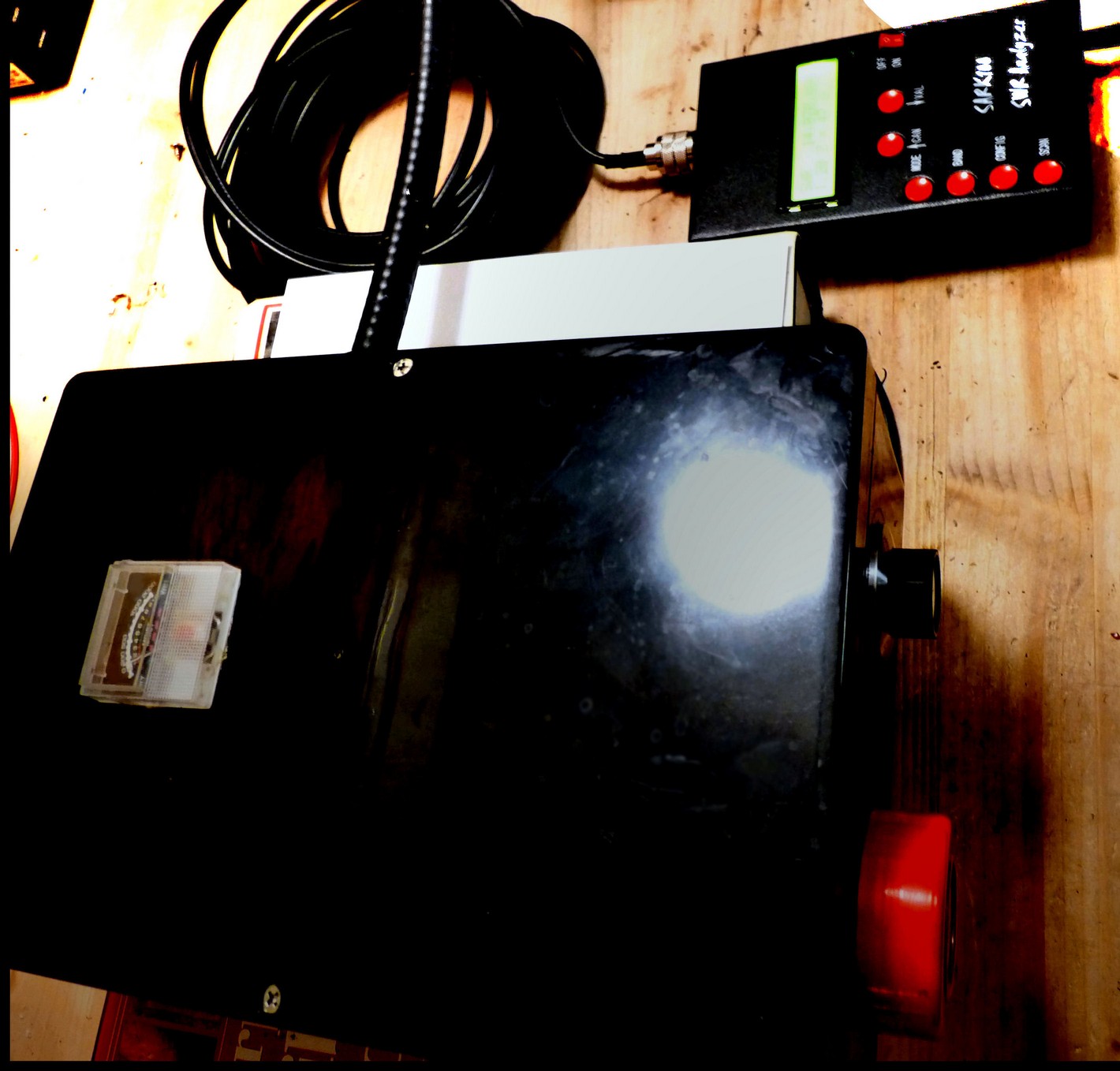
In picture 3, you can see the view from the operating position in my present Kelowna apartment.
Note that the stucco exterior wall finish is applied over a wire screen, creating a great Faraday shield (to keep desired signals out!).
Also we have a great view of the 1200 volt power line feeding a 120/240V transformer. (Is this still called a pole pig?).
As a bonus, we have both Telus and Shaw cable runs right out side our window. And of course such cables never radiate undesirable signals, do they?
Other apartments, on the five sides of my apartment have kitchen fluorescent lamps, TV sets etc. Designed to make shortwave reception an interesting challenge.
(The worst offender in my own apartment turned out to be the dishwasher!).
Pix4
Do small loop antennas show an advantage when used for reception in an electrically noisy environment? The answer is “perhaps”. (Consider the graph picture 4).
Most QRN it seems, is from an electrostatic source, like motors that have a sparking commutator, an electrical drill for example; or Plasma TV sets, or even computer processors etc.
Now (as you know), a radio wave is composed of both electrostatic and electromagnetic fields.
The difference between reception of a radio wave on a 1/2 wave dipole for example, and reception on a
“small loop”, (and in particular a “magnetic” small loop), can be significant.
Not only can you easily aim a small loop to increase the reception of the desired signal, but you also could rotate the loop to place a null on an interference source.
As well, the “magnetic loop antenna” is often less sensitive to the electrostatic field component of a radio wave than say a 1/2 wave dipole, or large antenna array might be. The distance from your source of electrical interference is significant. Have a closer look at the chart shown in picture 4.
That brings us to the question:
Pix5
What exactly is a “magnetic” loop antenna?
Essentially the difference between a small loop and a “magnetic loop” is that the magnetic loop antenna is usually no larger than 1/10 of a wavelength in circumference.
Most references suggest that would be a maximum diameter of about 1 M or 3’ when 20 meters is the target design.
What we are striving for, is the same amplitude of current flow in all sections of the loop. (or at least a balanced current at the opposite point across the loop).
It is also important that the loop be as conductive as possible. Copper or aluminum tubing should be at least 1/2” O.D. Smaller, hook up wire does not work well for a loop antenna. Some very successful loop designs are built with conductor diameter approaching 5”.
It’s the surface area that is important. Copper or aluminum conductor works, and the larger the surface area, the less difference I would expect to see between copper or aluminum in the ultimate performance.
Many design ideas are shown on U-tube or in the ARRL Antenna Manual, (and I suggest you do lots of “doodling” on paper, before beginning actual construction using your available materials).
Pix6
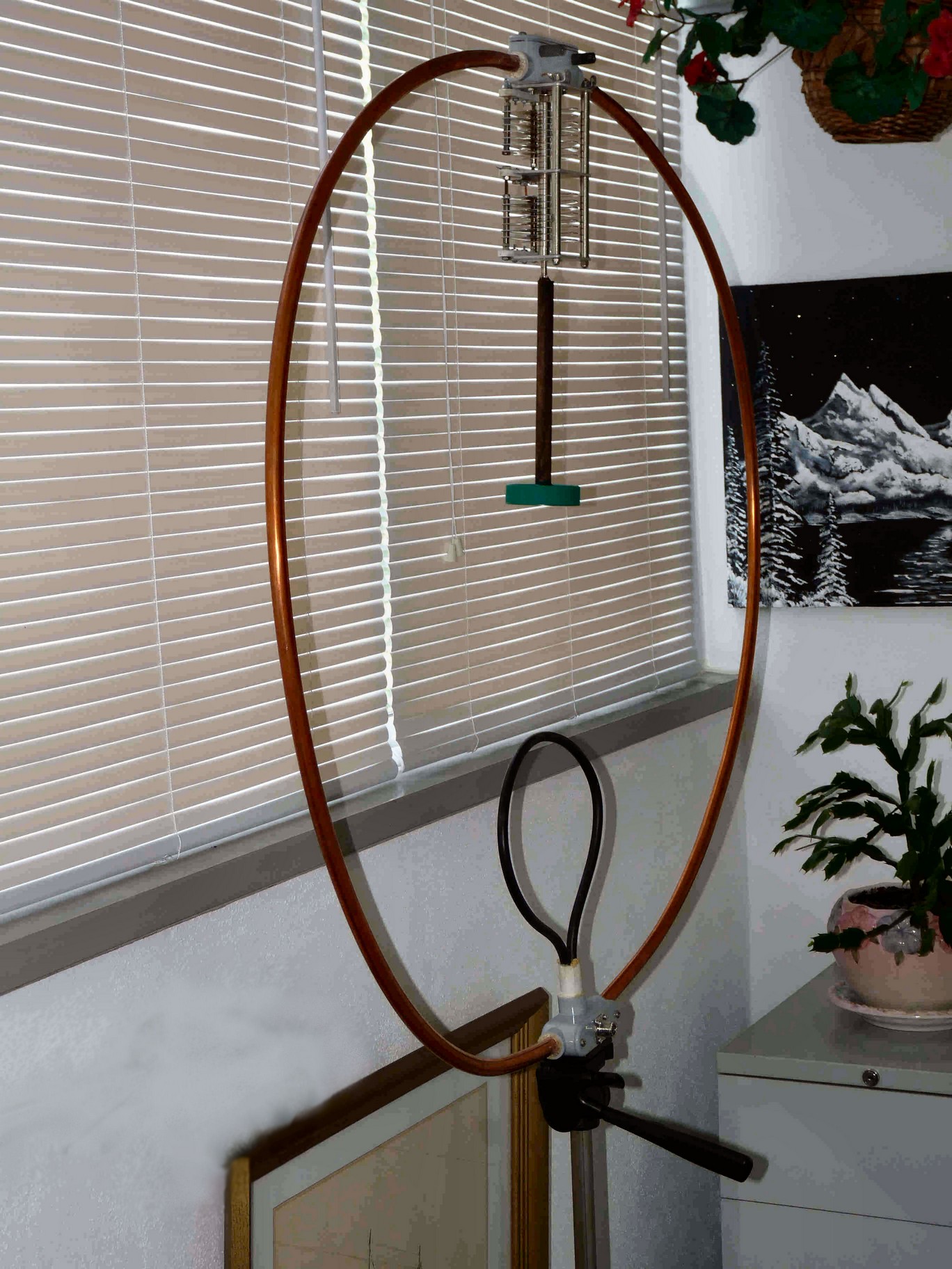
The picture above is of a simple magnetic loop antenna built for 20 meters.
The small “black” loop at the bottom is the primary loop. It connects to the coaxial feed line coming from my transceiver. This “primary” loop is about 1/5th of the size of the secondary loop.
This primary loop is formed from #4, insulated service entrance cable wire.
The secondary loop in this antenna is made from copper tubing just over 1/2 inch in diameter. It is readily available in 10’ lengths of tubing and can be formed by hand into a circle.
At the open ends (the top of the secondary loop), I connected a variable capacitor rated at about 250 pf max and perhaps capable of handling 2000 volts of RF. The voltage can be quite high at this point if you are applying significant power from your transmitter.
Pix7
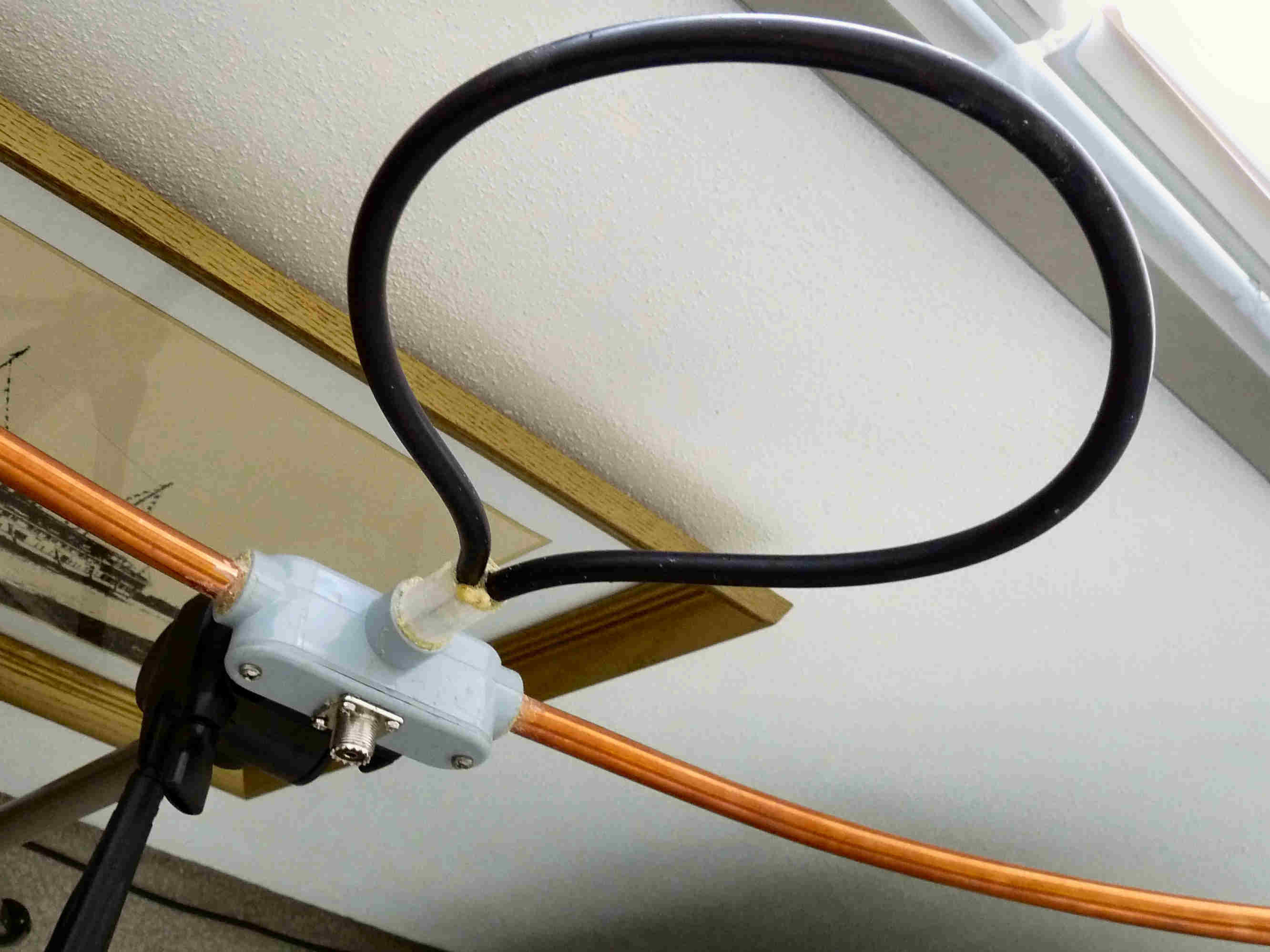
The pix above shows the bottom of the loop assembly. I used standard electrical components from the hardware store. The RG8 coax input is attached directly to the relatively small primary loop via an SO239 fitting you can see at the bottom.
Pix8
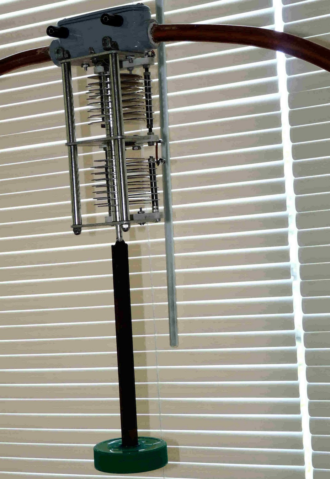
Shown above is a close up view of the air dielectric variable capacitor attached at the top. That is, to the open ends of the 3’ diameter secondary loop. The two black connection points at the top of that assembly are to allow the addition of a parallel fixed capacitor for lower frequency resonance trials.
Pix9
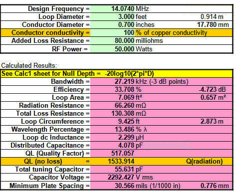
Various examples of “free”, loop antenna design software can be found on the internet, and they can be useful in predicting transmitting efficiency and the bandwidth of a loop antenna.
An antenna constructed like that shown in pix7 is rather impractical for SSB phone on frequencies lower than 40 meters due to its relatively high Q. (and the resulting very narrow bandwidth).
Observe also, in this example, the calculation shown for capacitor voltage generated when operating with a 50 watt radio transmitter.
Pix10
Illustrated is a home made “tin can” capacitor. It was added to tune to a lower frequency. (approx 300pf at 2KV in this example).
Pix11
This picture above shows an example of a small “double” loop 20M antenna built with two goals in mind.
Radio energy tends to travel on the surface of a conductor, and also the larger conductivity of the parallel copper tubing offers less “ohmic” (loss) resistance and therefore more radiation efficiency.
Note that “solid copper” pipe hanging strap, was used for the primary loop in this construction. Some copper strapping being sold is only plated copper over iron – be sure to get the better stuff!
Pix12
Picture 12 above illustrates a full size version of the double, (3’parallel loop) “magnetic loop antenna”.
An SWR bridge was added, and the antenna designed for a “plug in” primary loop to allow experimentation for optimization of the coupling impedance that is different on each ham band.
Originally the design was also to allow easy switching of the secondary loops to be in either parallel, or in series for low frequency tuning experiments. But lower
frequencies proved impractical (at least for phone), due to bandwidth limitations.
The black cube to the left of the SWR meter in pix12 is a ferrite cube on the RG8 co-ax, to reduce feed line surface current.
Pix13
Eventually the design was returned to the larger copper strap primary loop conductor, optimized in size for 20 meter coupling to the secondary parallel copper tubing elements.
Pix14
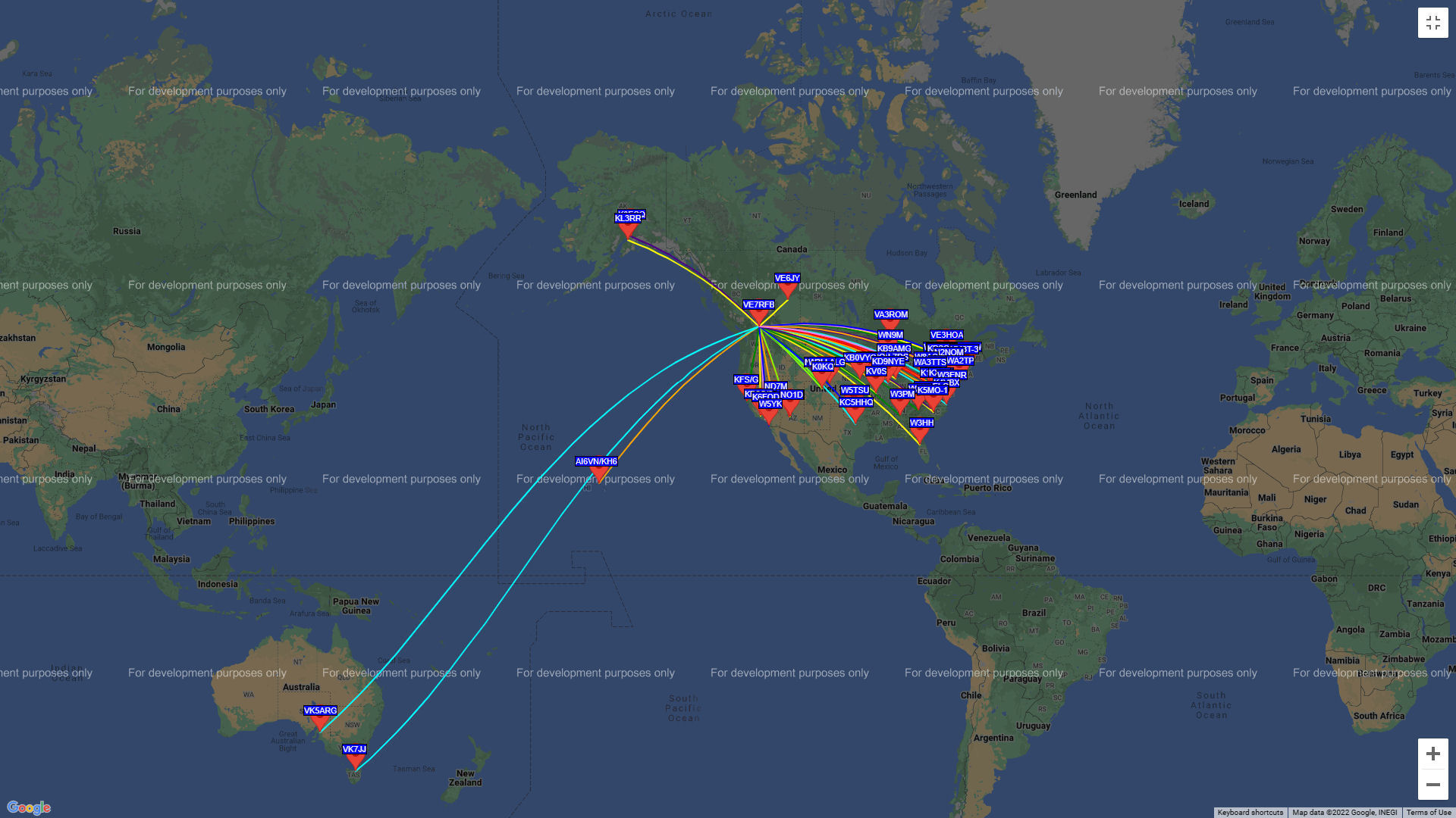
Over all, the results
obtained with this loop were encouraging. This is a typical daily WSPR map result at my location while running 5 watts on 20 meters over a 6 hour period. Maximum effectiveness agrees with the direction arc view that I can see out of my window.
Pix15
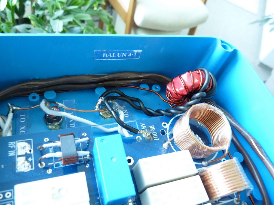
The urge to build a magnetic loop antenna that incorporated automatic tuning, resulted in the blue box version depicted here.
Pix16
The essential component ATU kit, bought on line contained relays, capacitors, coils etc. to be added to the supplied printed circuit board that had surface mount components pre-installed.
This design included a digital display and circuitry for SWR measurement. A nice and useful feature.
Pix17
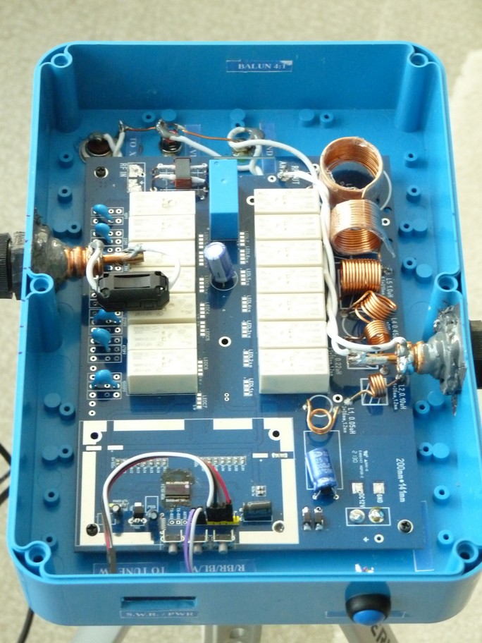
Above, (in Pix 17), is a top view of what the assembly looked like as final construction was approached.
Originally, the main (secondary) loop was made with 5/8”diameter Heliax attached to the blue box with type N coax connectors. This proved unsatisfactory as resistance to any axial rotation of the Heliax (while being transported for example) was insufficient.
Eventually I substituted cable entry glands fixed by epoxy at the inside of the blue box; but this precluded easily modifying the loop size.
This design did tune on multiple bands, but SWR was generally in the 3:1 range.
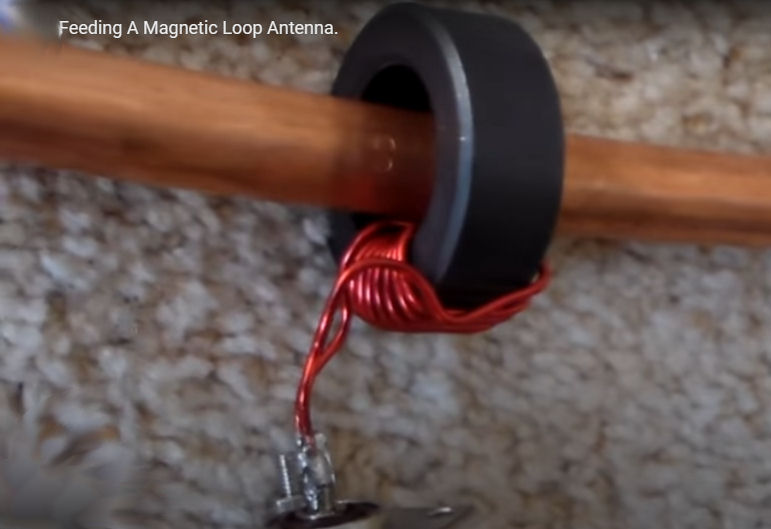
Pix18
I decided to add a “tuned” type 43 Toroid, optimized for 20 meters, at the ATU output, coupled to the loop as shown in this picture, and this design is also shown in the following schematic drawing.
Pix19
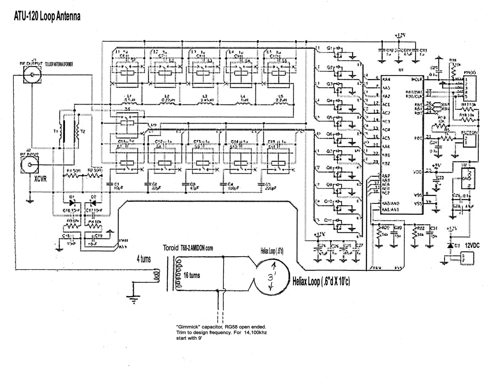
The term “gimmick” capacitor noted on this schematic may be unfamiliar to you. It refers to a capacitive feature usually made by twisting two insulated wires together, to change the capacitance portion of a tuning circuit, or sometimes made by cutting a coaxial cable length to the point where the inner conductor and outer shield together form the required capacitance.
Pix20
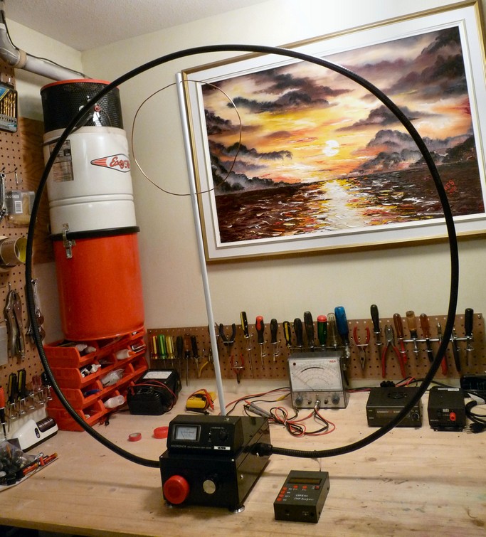
The picture above illustrates an iteration of the magnetic loop design that will withstand higher power. (at least 200 watts of continuous RF power).
An SWR bridge was built in to aid in design and positioning of the primary loop, relative to the maximum current point of the 3’ diameter secondary loop.
The correct size, position and angle of the primary loop proved elusive. And the mechanical design proved somewhat unstable.
Pix21
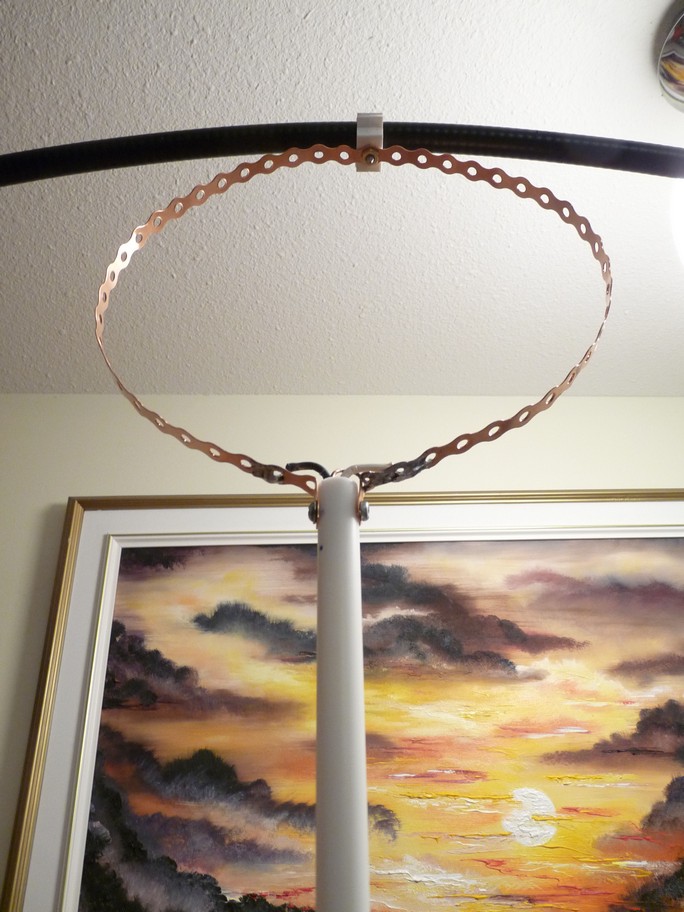
This picture shows the best compromise I found for this arrangement.
Pix22
Somewhat better results and superior mechanical stability, was achieved with Toroid coil coupling at the max current point (in this instance at the top) of the secondary loop.
Pix23
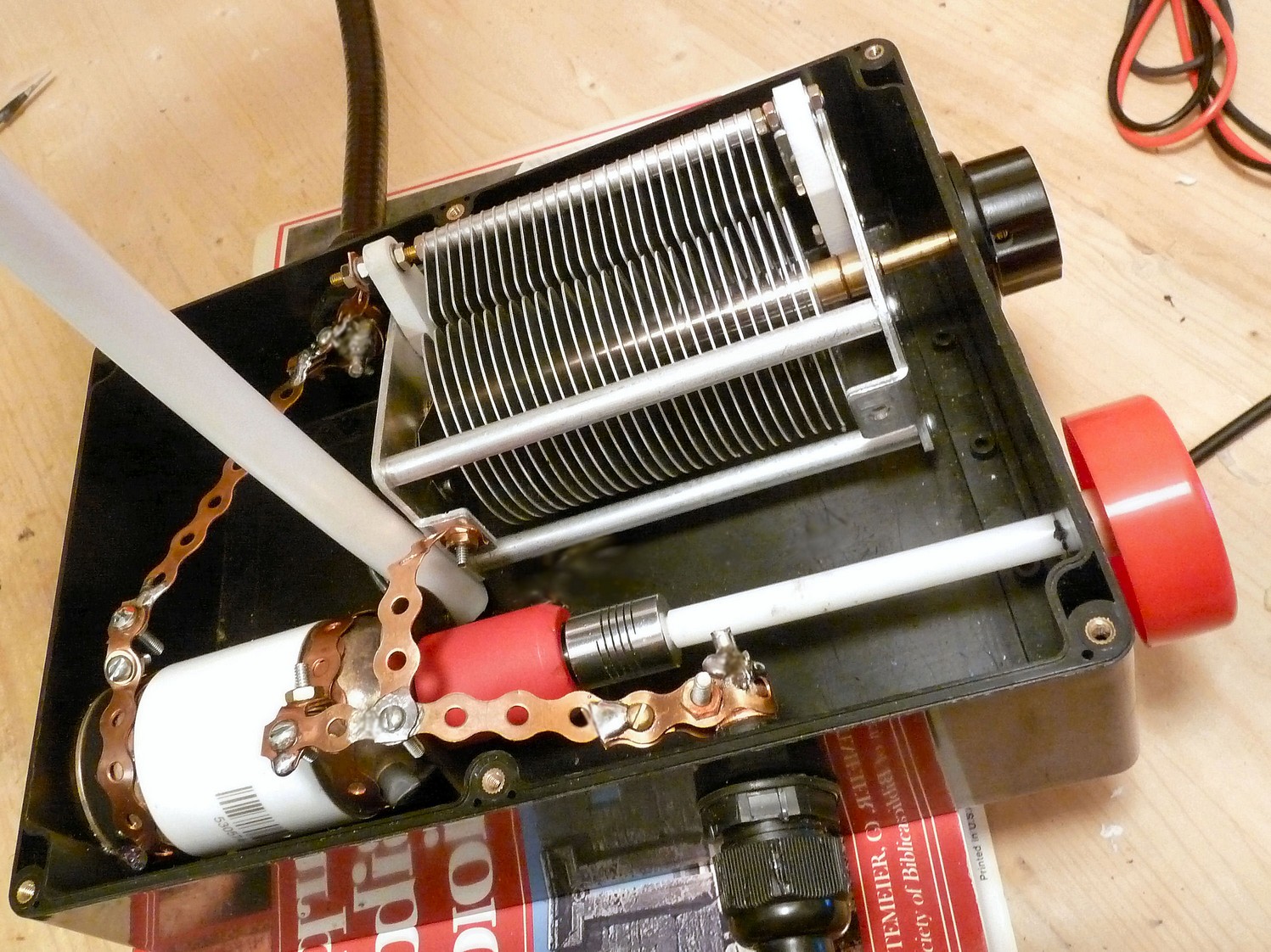
This view show the internal construction of the loop tuning box described above. The lower, white and red unit seen is a vacuum capacitor rated at 30-350pf and 4000 volts. The air dielectric shown near the top is about 250 pf max and will tolerate perhaps 2000 volts.
Inter connection was made with solid copper, pipe strapping material.
Space for a future possible motor drive of the vacuum capacitor was left at the bottom right of the plastic box.
Pix24
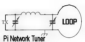
Eventually it was decided that a Pi section tuner connected directly between the input RG8 co-ax and the
3’ diameter Heliax loop, was the optimum approach for my 20 meter magnetic loop antenna.
Pix25
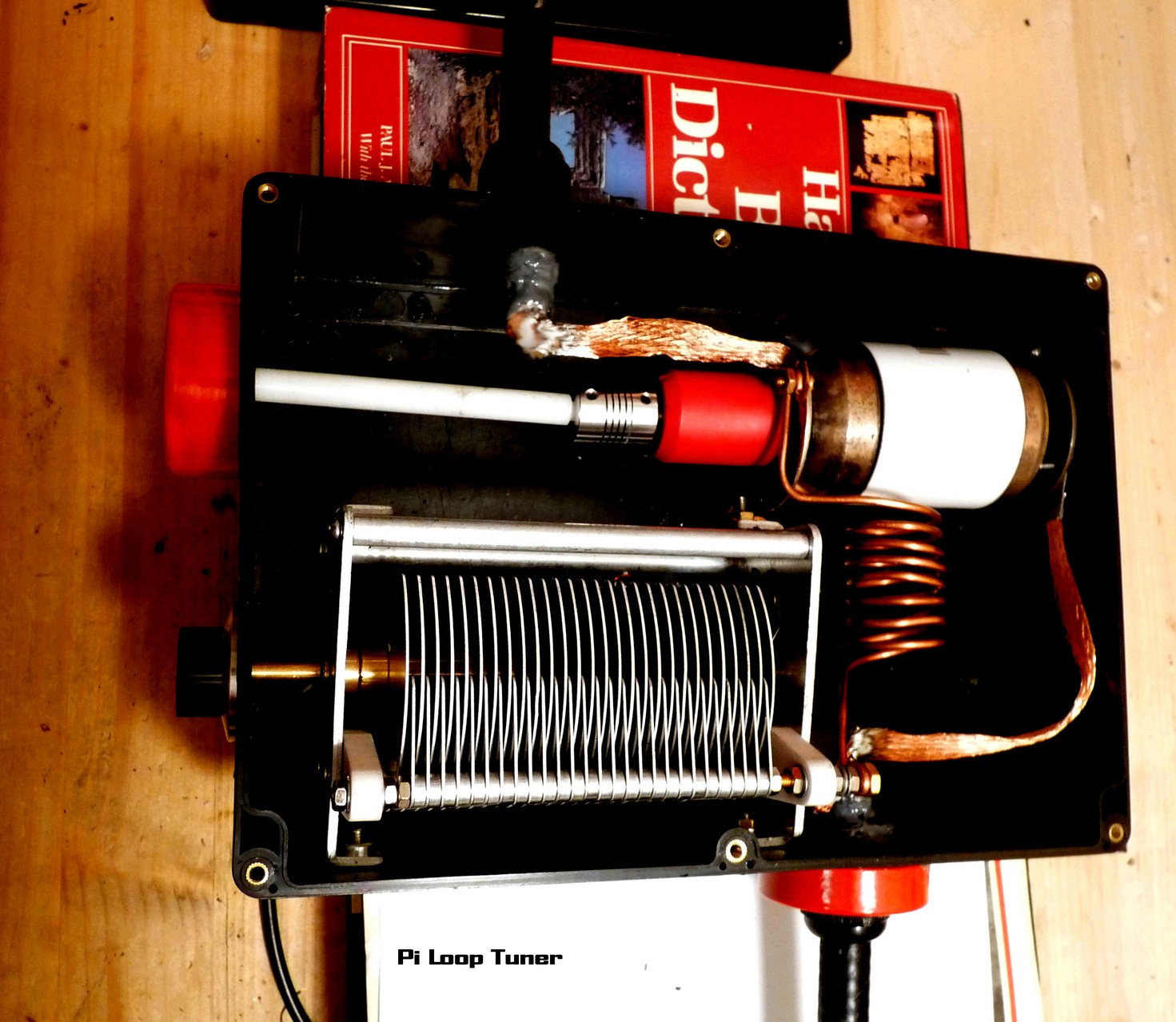
This picture shows the final construction. Copper braid was substituted for the copper strapping used in previous designs.
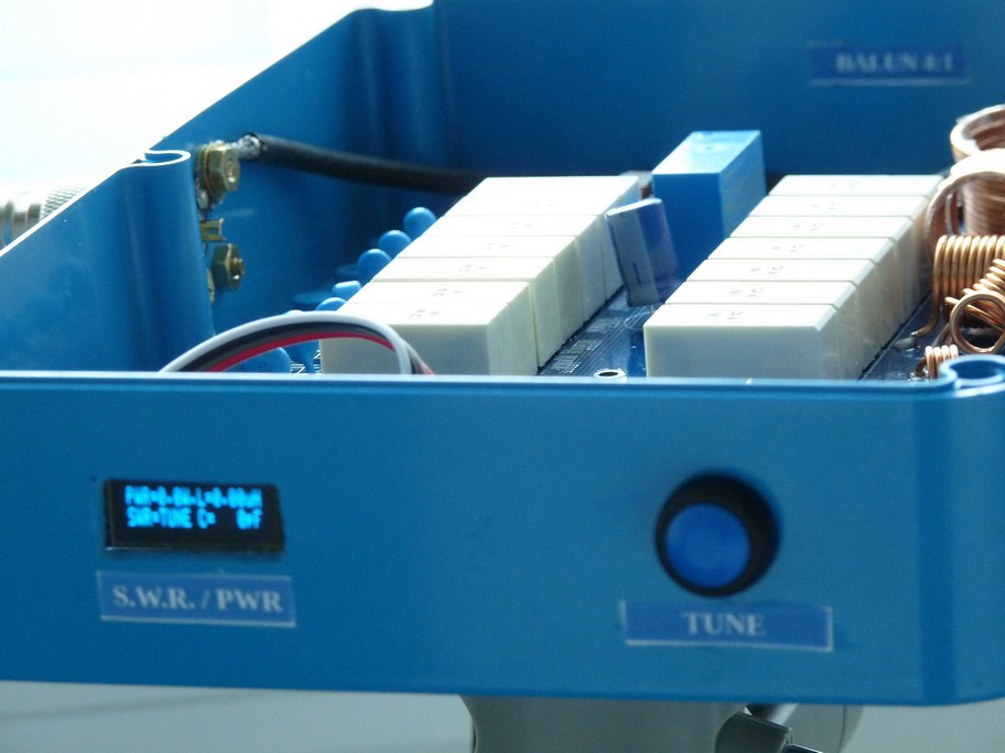
Pix26
A simple field strength meter was built in to the top of the enclosure to aid in tuning. Initial tuning however is
usually chosen for maximum background receive noise at the desired frequency.
Pix27
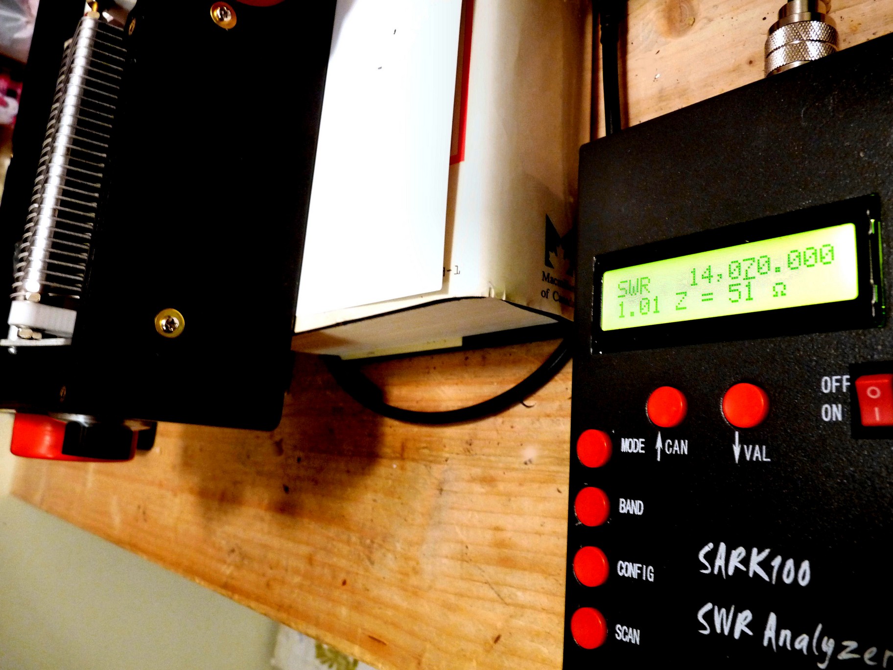
The final result of this construction project is displayed on the Sark100 analyzer, and that seemed like a good place to pause this project.
Ron ve7rfb
Sphere Research and OCARC will host a dual Stuff Day/Amateur Radio Swap
For more information https://www.ocarc.ca/stuffday

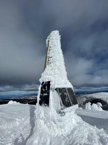
Some snow was removed from the solar panels at Little White today.
The course is now full. Thank you for your interest and registration is now closed.
Watch our website for notices of future courses.
Amateur Radio Basic Qualification Course
Are you interested in joining the ranks of Ham Operators around the world?
OCARC would like to assist you in anyway we can to achieve your goal. (Email links corrected 2022-12-11)
These include:
1. A formal course – OCARC is currently running a Canadian Amateur Radio Basic Qualification course, commencing January 18, 2023.
Let us know if you are interested by contacting us at ocarchamcourse@gmail.com
2. Study materials - We have copies of Canadian Amateur Radio Basic Qualification Study Guide for sale - this saves you paying the shipping.
3. Fellowship - you are always welcome at a Club event. Come to a monthly meeting, at the Main Firehall, fourth Thursday at 7:30 PM.
The cost is $100, this includes books & course materials, pays for part of the room rental and the remainder of the current year's OCARC membership. The exam is free.
Radio Amateurs of Canada (RAC) is the national organization representing Hams across Canada. A great place to start is RAC's website: https://wp.rac.ca/how-to-start/ Here you can find resources for getting your certificate. While there, be sure to download a copy of the ExHAMiner. This software will create an exam with questions from the actual exam. You can practice taking the exam and be able to determine which topics you need to study or need assistance with.
How to Sign Up
Please email our Education Coordinator at ocarchamcourse@gmail.com
Wayne is organizing an OCARC Christmas dinner at the 88 Grand Buffet on Thursday Dec. 8 at 5:30 PM.
88 Grand Buffet is located at 2339 Hwy. 97 North, Kelowna. Their website
As seating is limited, contact Wayne at bignellwl@shaw.ca to save your seat. No tickets required, just contact Wayne. Open to members and their spouses.
CNIB is requesting a donation from our club. We are not in a place to respond directly to the request but we have in the past undertook to receive and forward donations from the membership. Without in person meetings the logistics of this are difficult.
If club members would like to donate to CNIB please visit their website and click on the Donate button in the upper right corner of their webpage.
Their Amateur Radio program provides:
 |
 |
 |